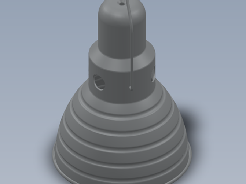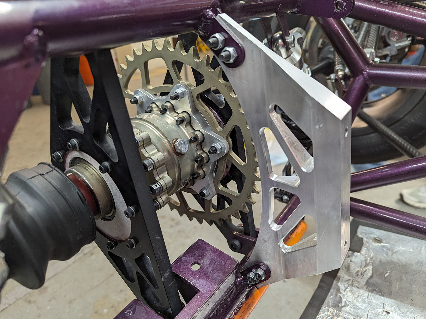
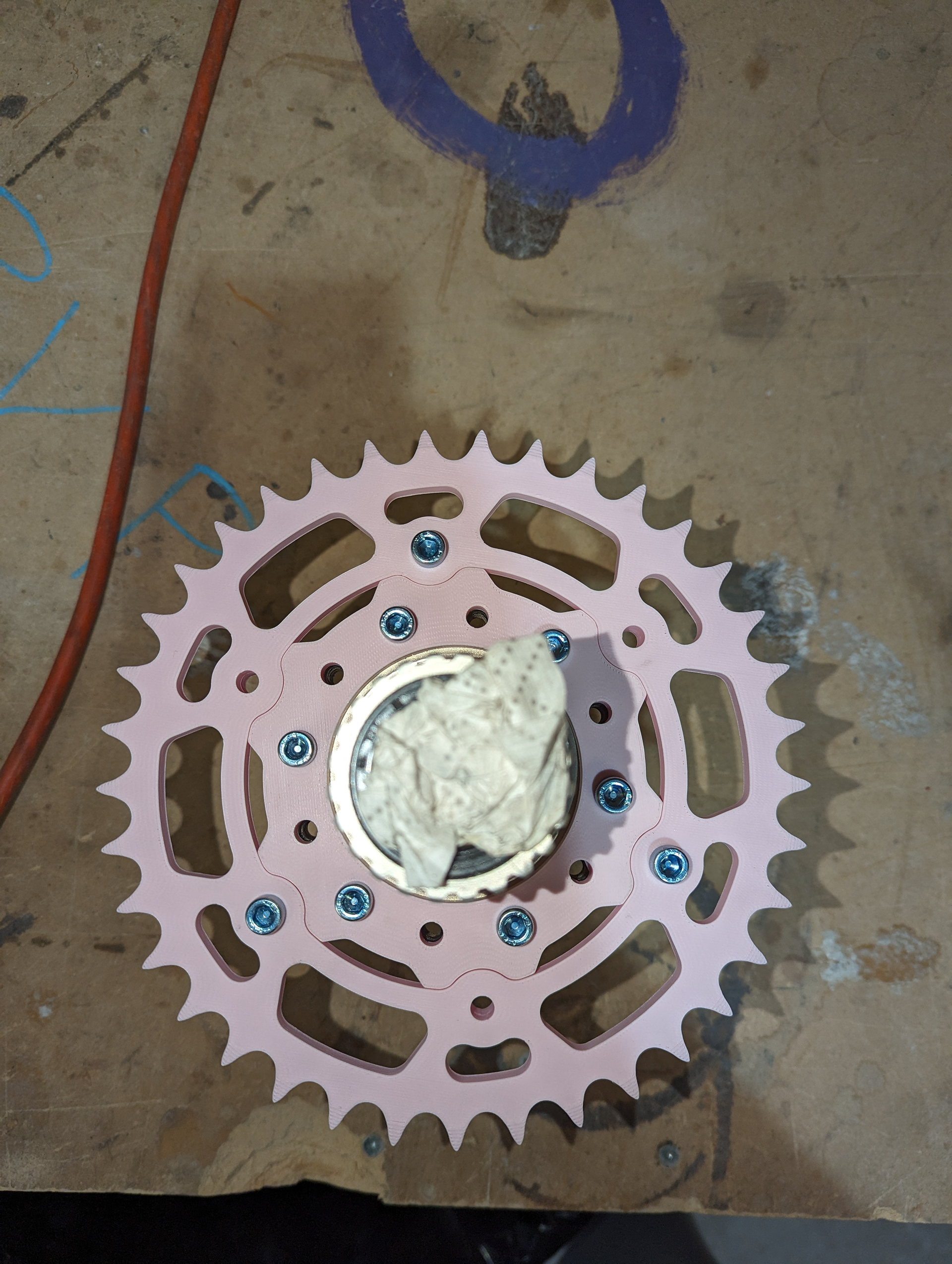
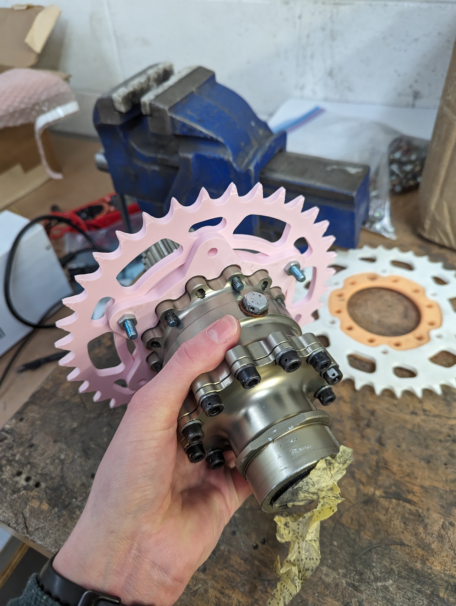
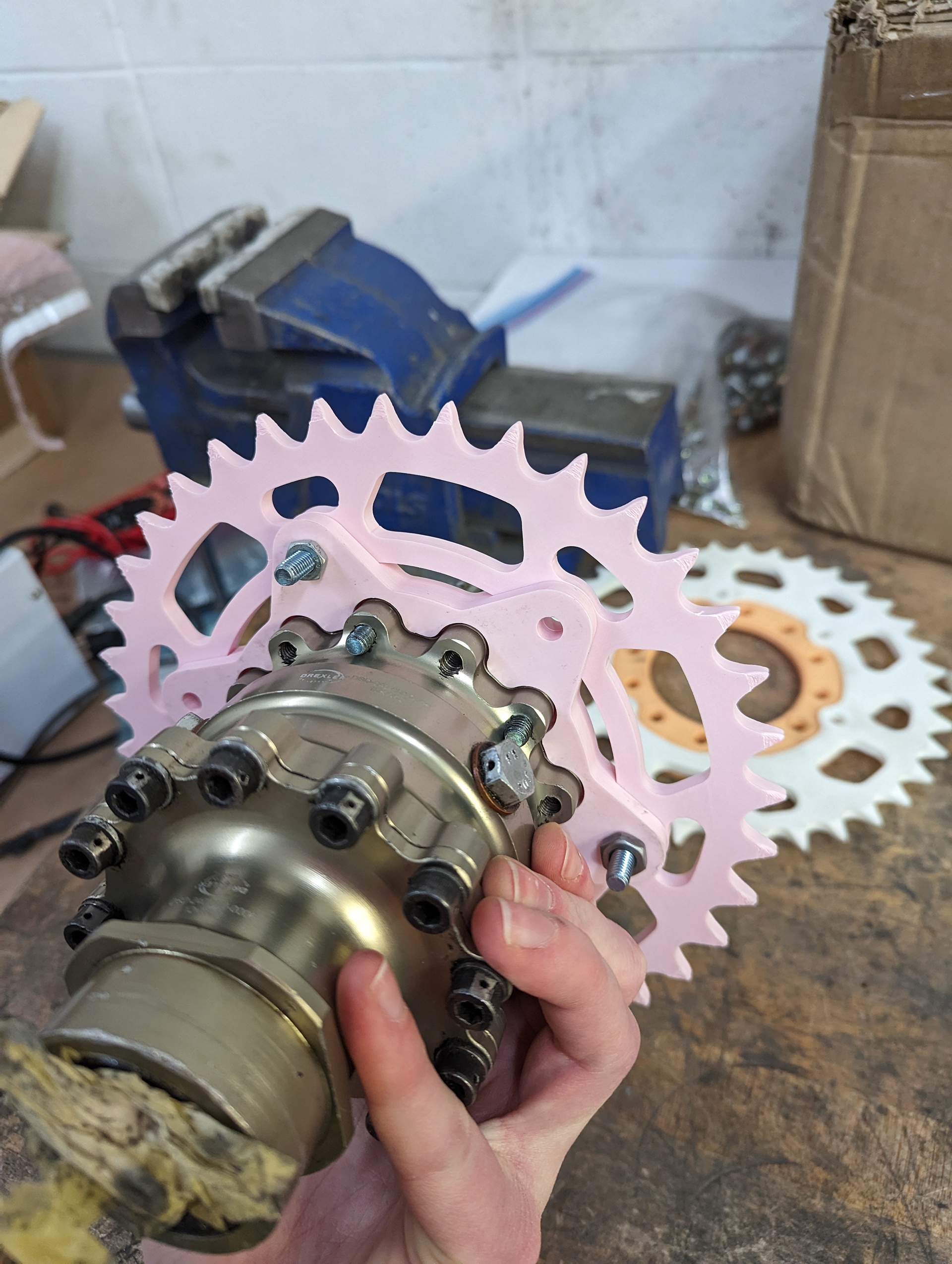
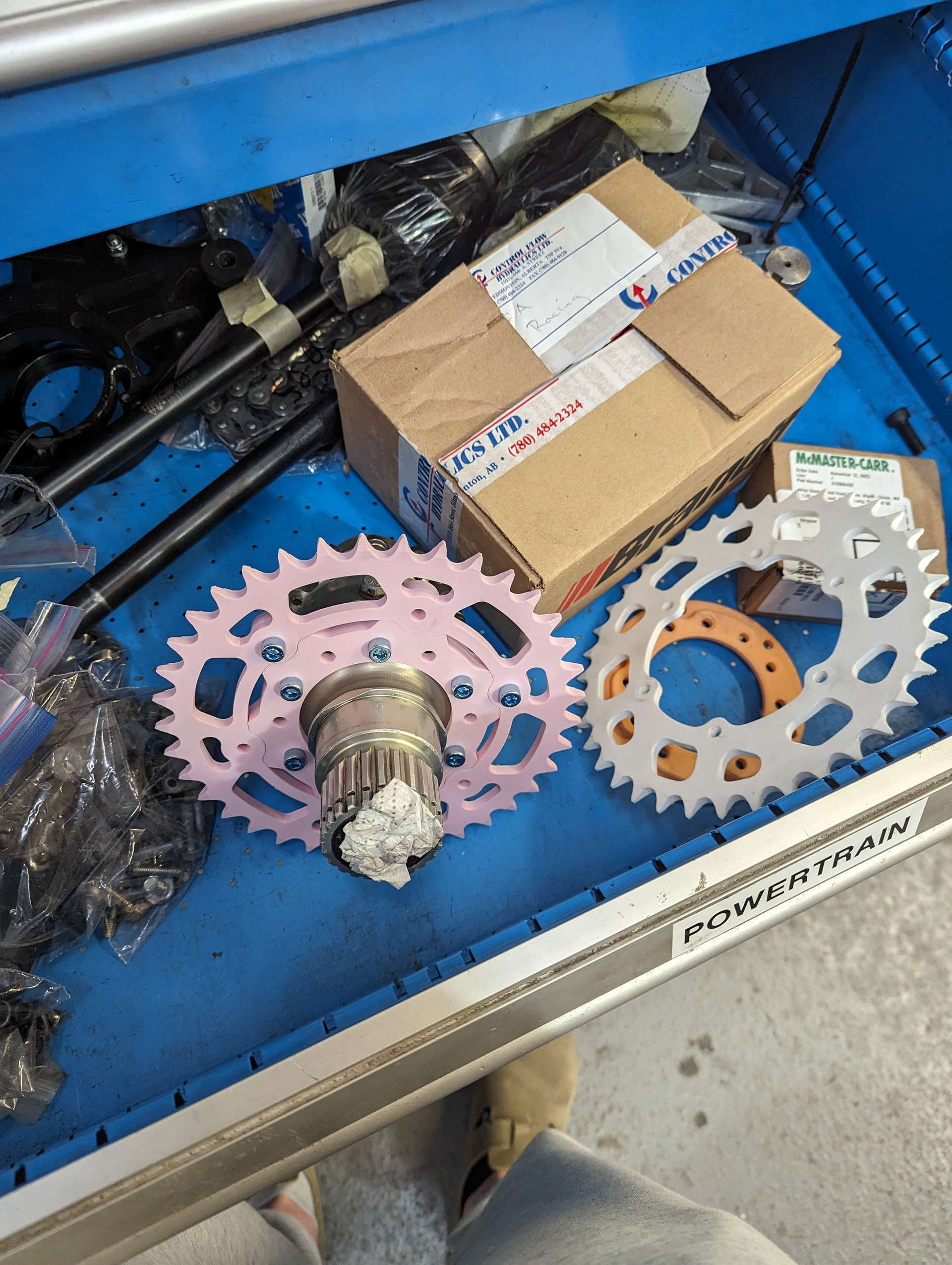
Below are pictures of the 3D printed prototypes I made to verify assembly fit with the actual differential and to decide the sprocket lightening hole geometry.
The number of teeth on the sprocket model was designed parametrically so it is easier to make a interchangeable set of them to vary our drive ratio for the different races. Please note that the ones pictured in these prototypes actually have 37 teeth so the part could fit on the print bed as a single piece, but we will be getting a set of 39T, 40T, and 41T sprockets machined.
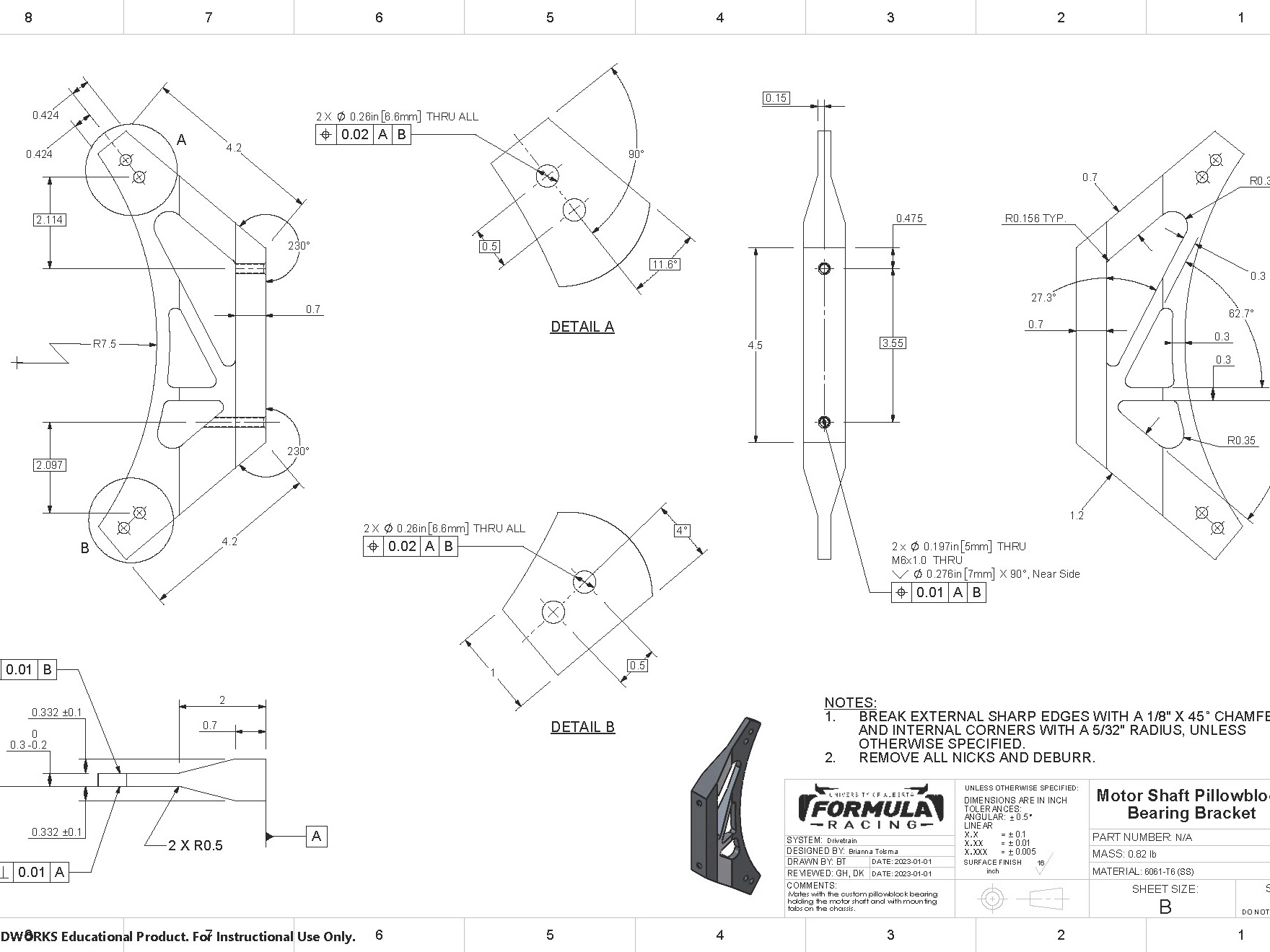
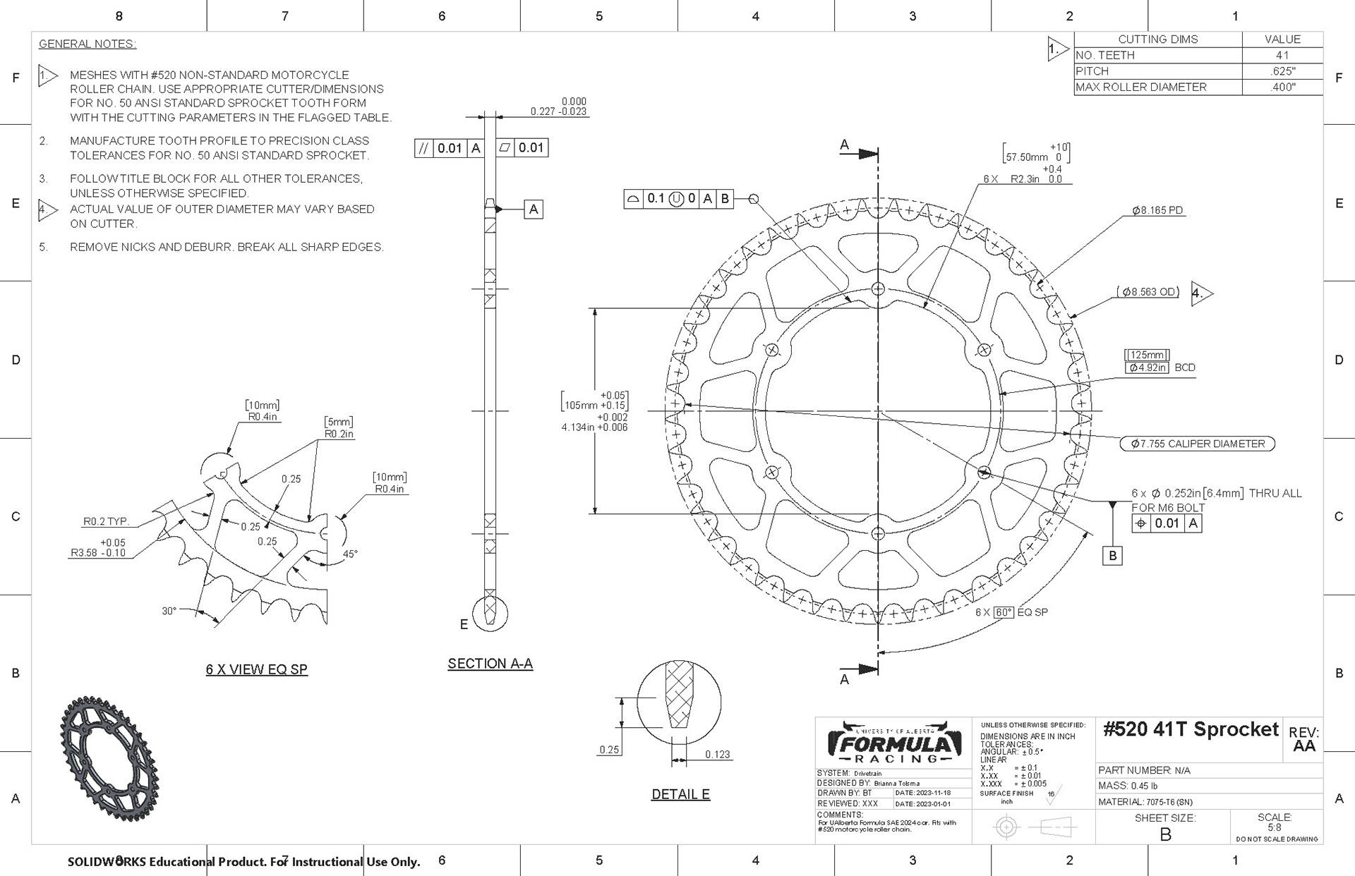
Below are the drawings I sent for machining for the adapter and 41T sprocket.

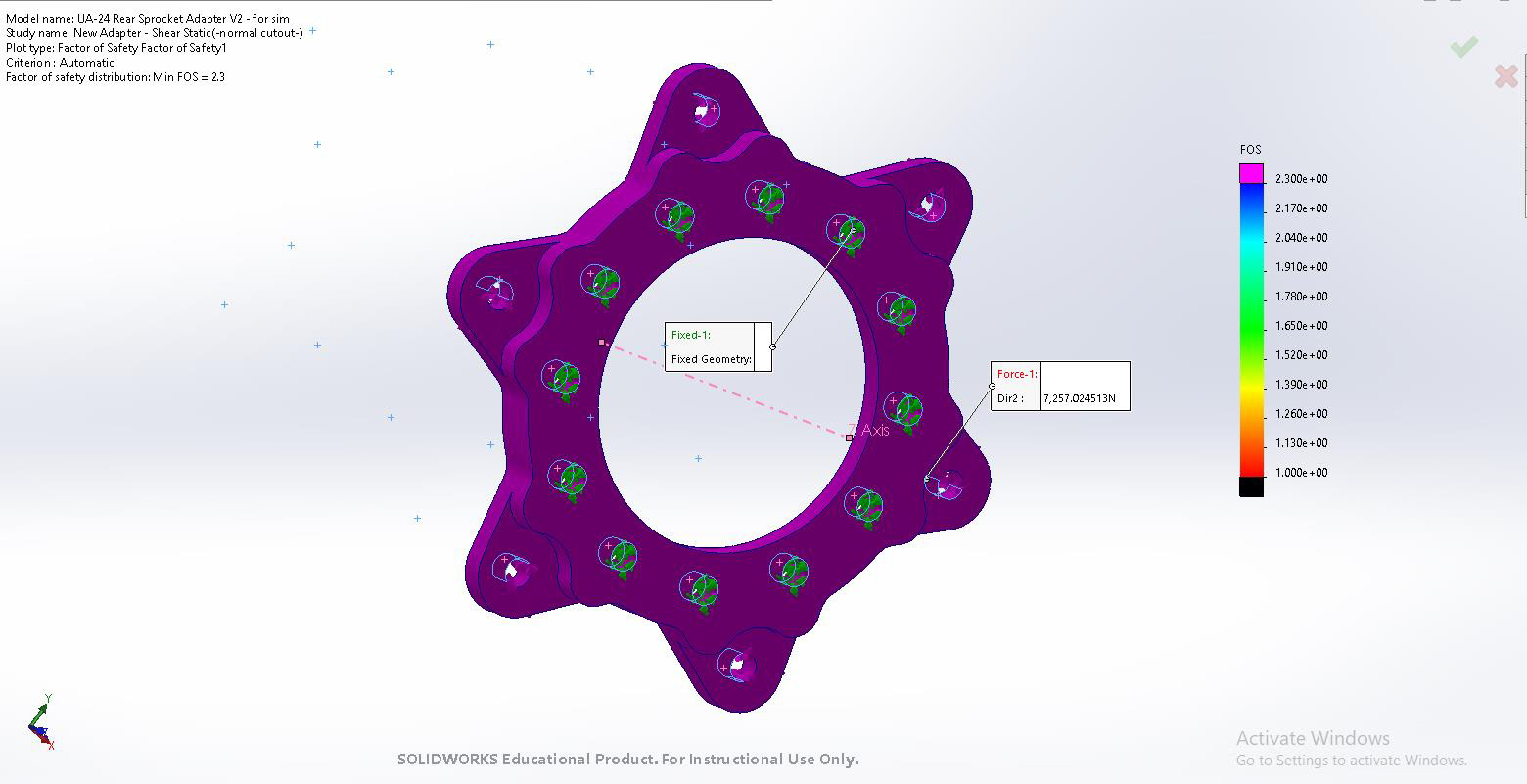
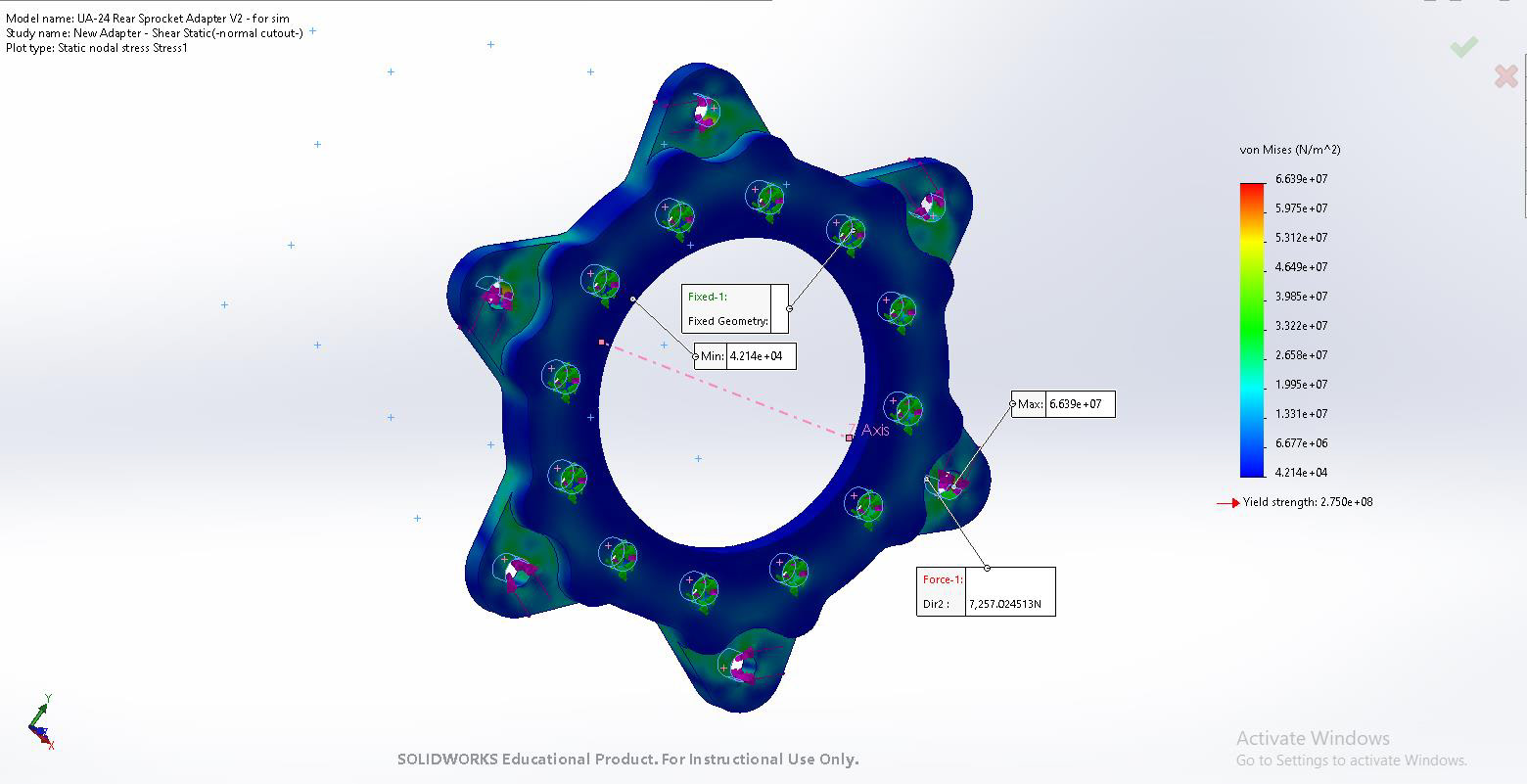
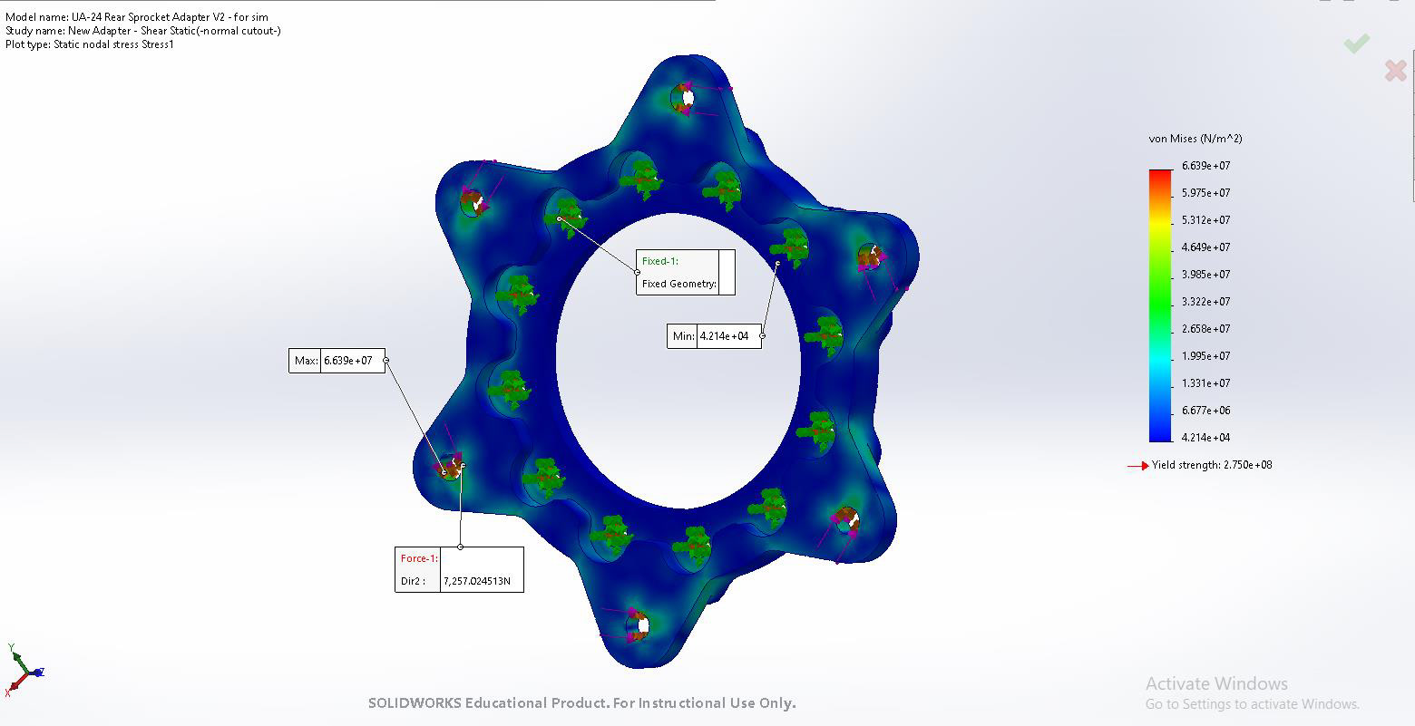
Below are screenshots from one of the preliminary FEA analysis' I performed to verify the adapter is strong enough to withstand the maximum possible loading condition before the chain will break, which was assumed to be when the motor reaches its maximum torque output but the wheels do not spin. It resulted in a FOS of 2.3. The sprocket (not pictured) passed a similar analysis with a FOS of 2.7.

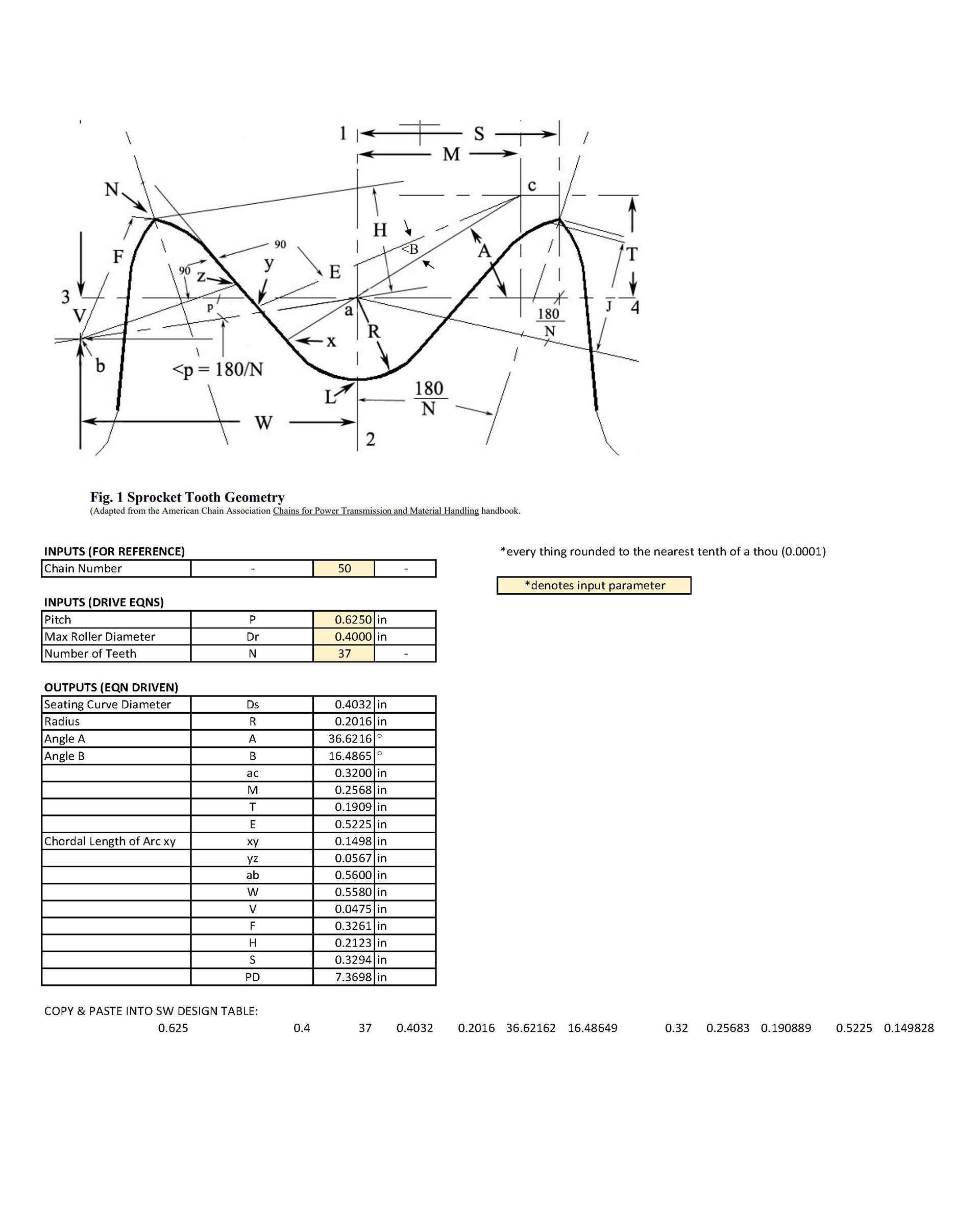
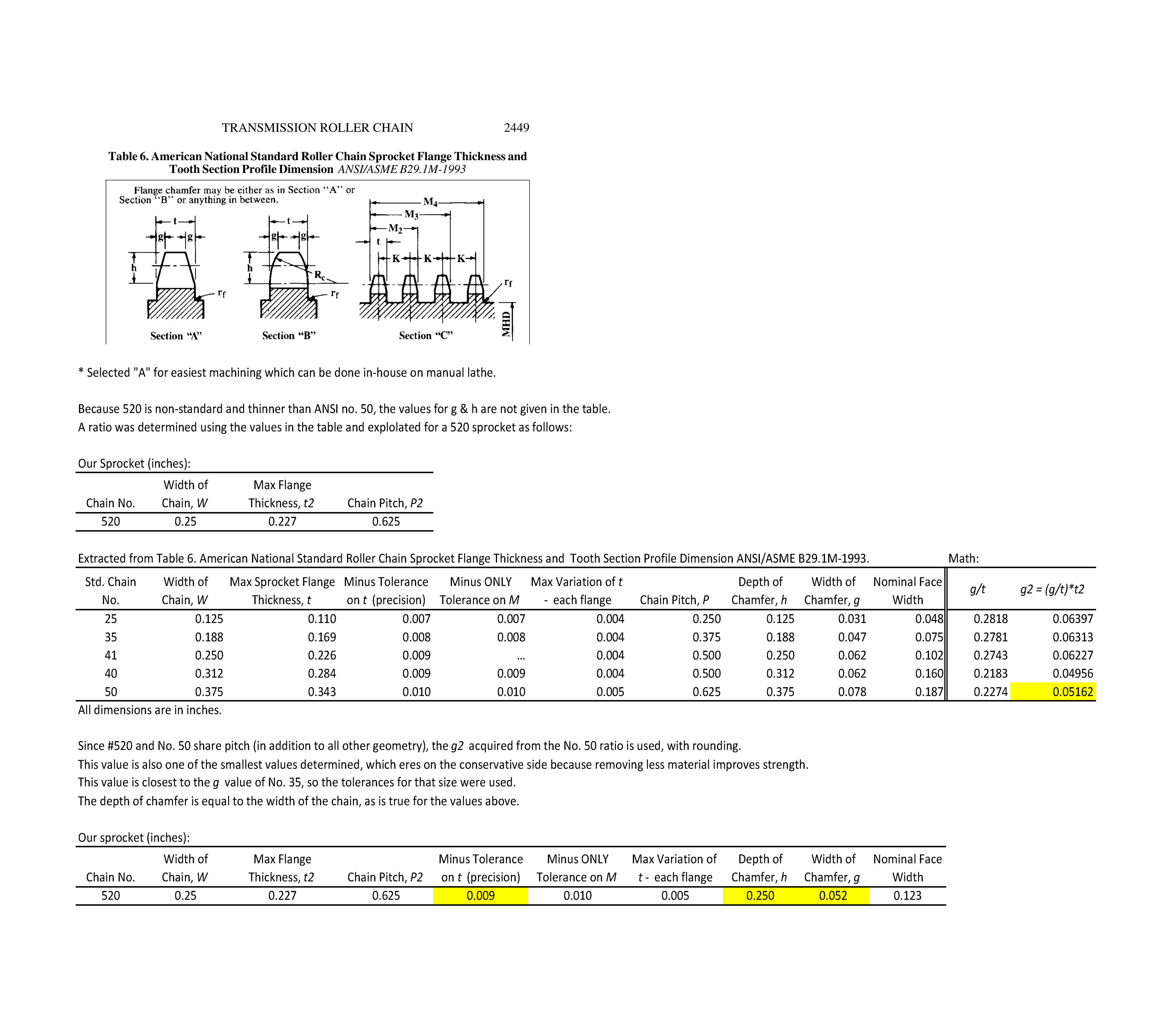
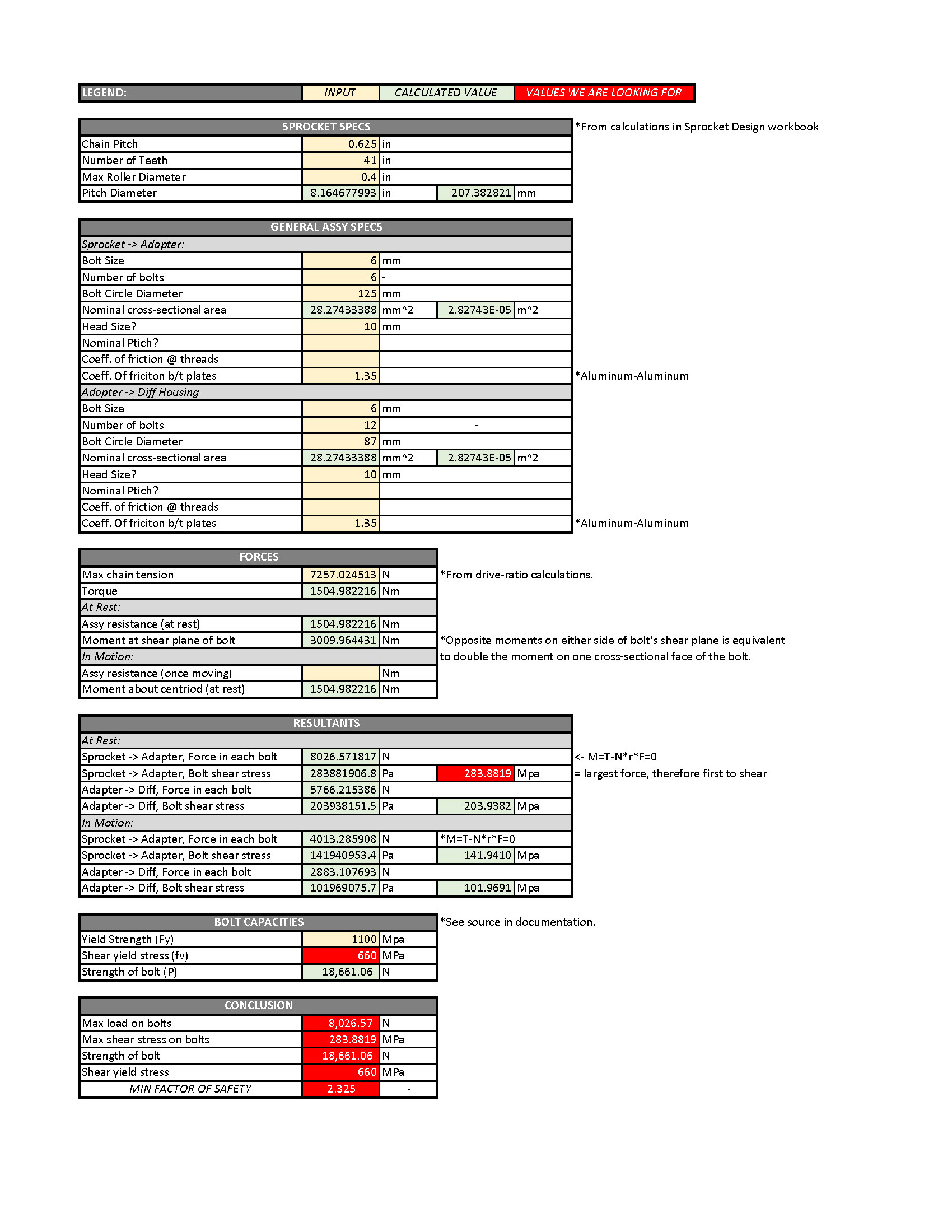
Click to view the following images of the worksheets I created for the sprocket design parameters and to verify the bolts are strong enough to withstand the shear load.
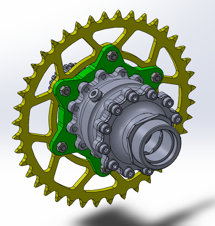
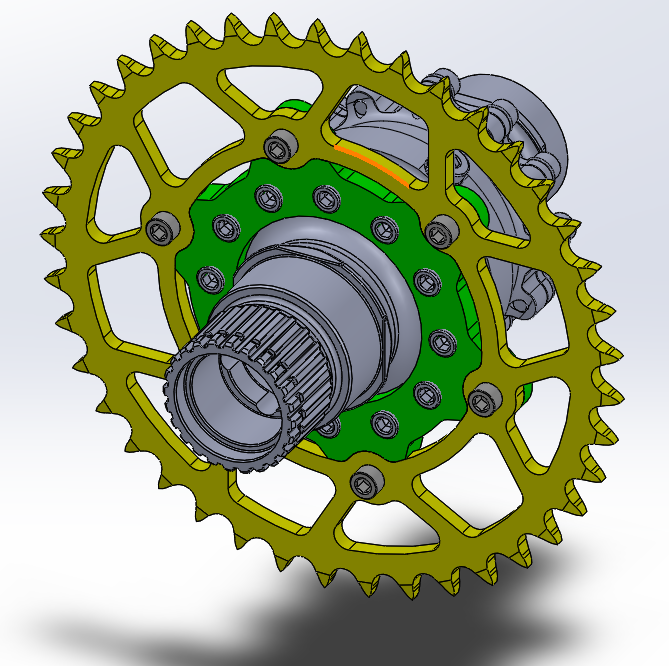
And lastly, here are some interactive views of the parts: