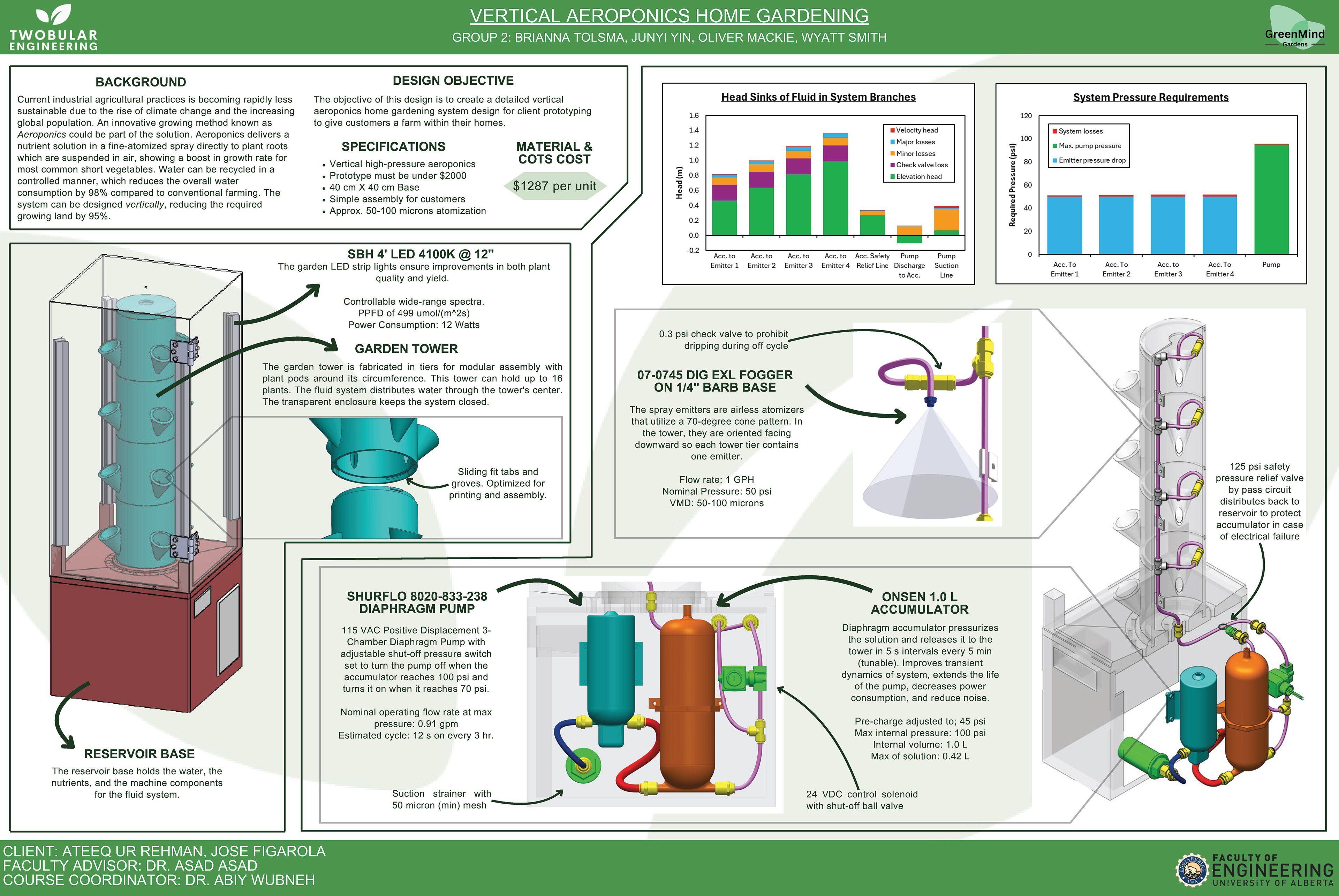
For my Bachelor's of Mechanical Engineering Capstone project, my group designed a small-scale, high-pressure atomization aeroponics device for our client, GreenMind Gardens. I was the Team Lead and the irrigation subsystem designer.
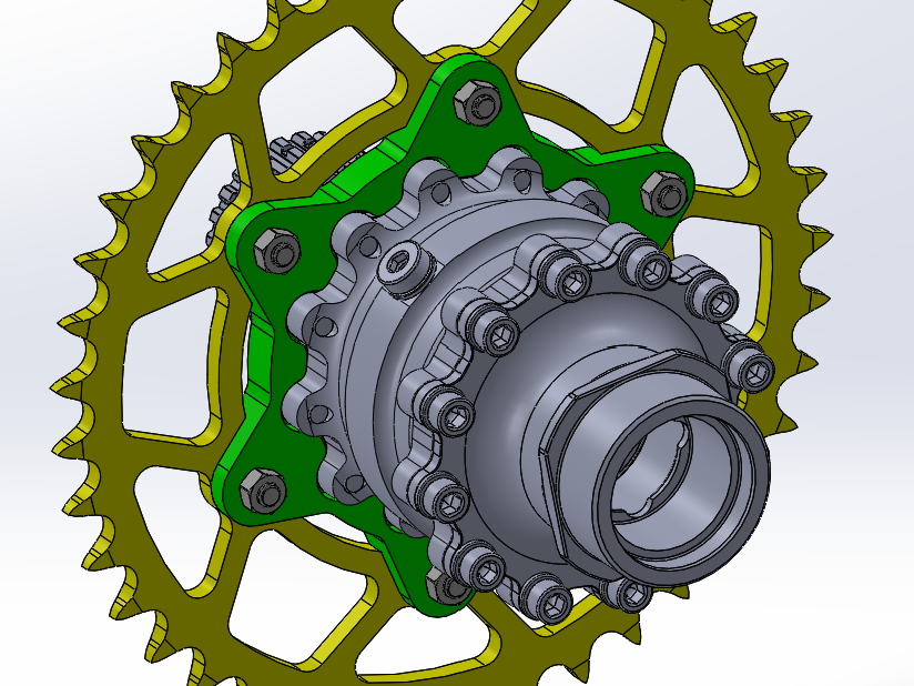
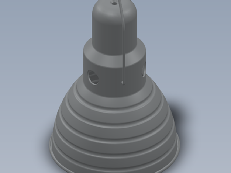
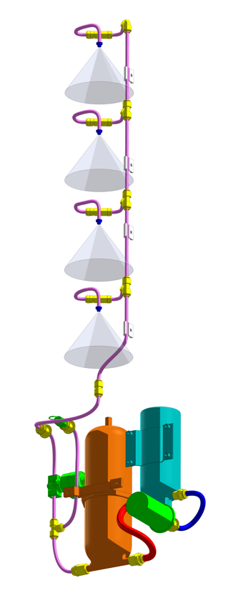
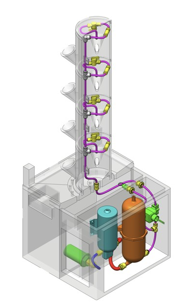
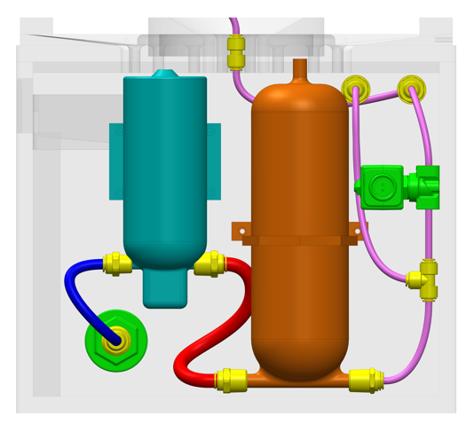
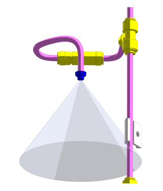
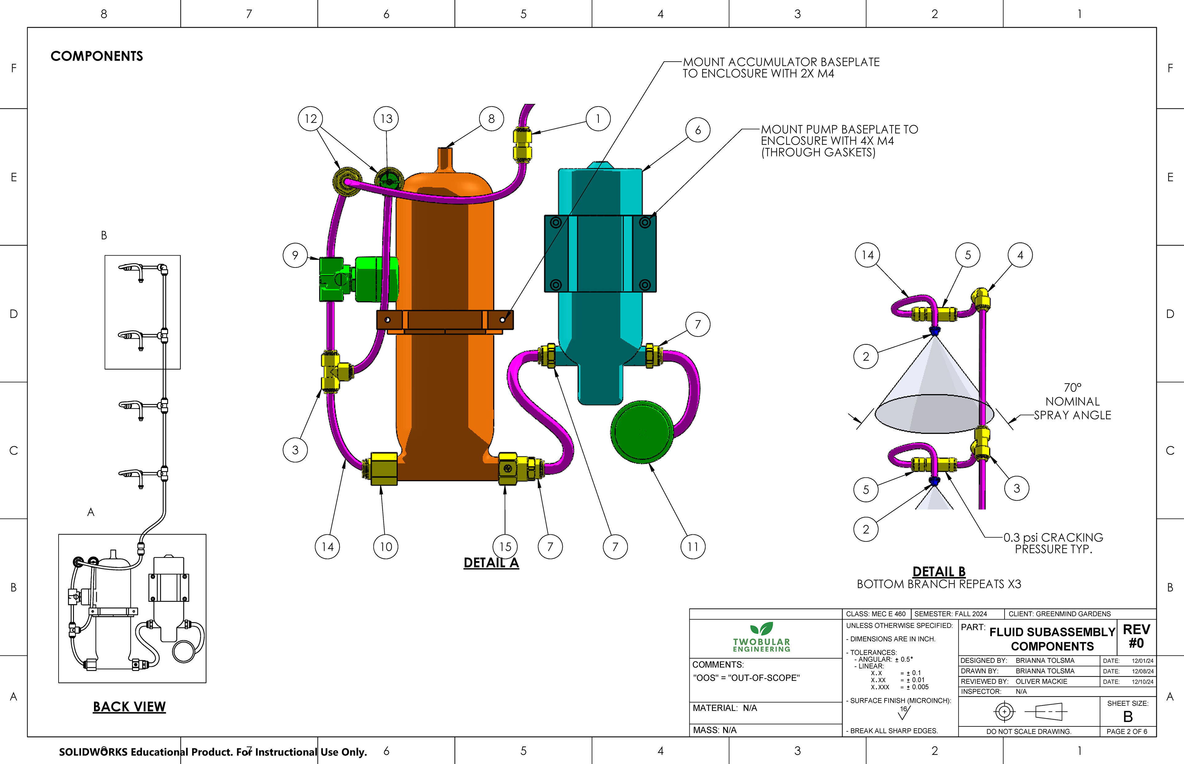
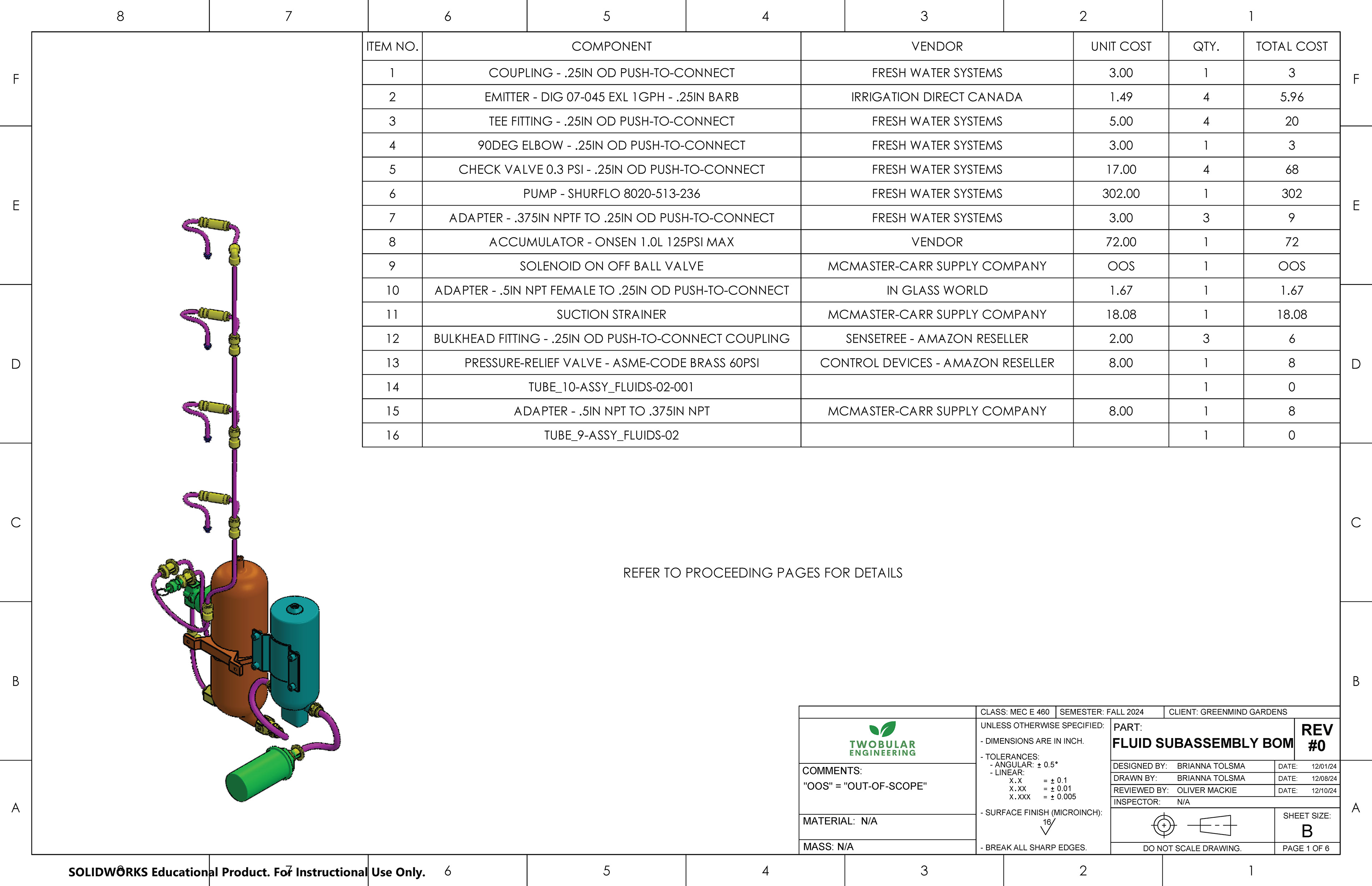
One of my responsibilities was to make the CAD subassembly shown below. I reverse engineered selected off-the-shelf components from their specification sheets where necessary, or found example models online. I placed them into the top level enclosure assembly that another member made using envelopes and in-context reference sketches to reduce the computational requirements and make the subassembly easier to modify as components changed. Then, I created connection points and used the Routing add-in in SolidWorks to model the tubing.
Note: Click on the images to enlarge them.
The selected components and operating parameters were based on the results of the analytical work I also completed earlier in the project.
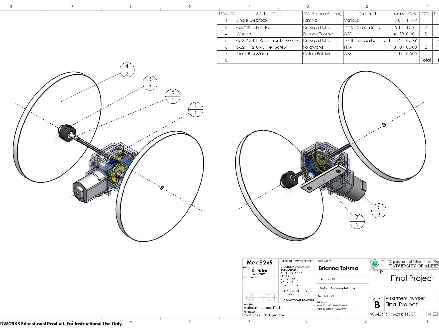
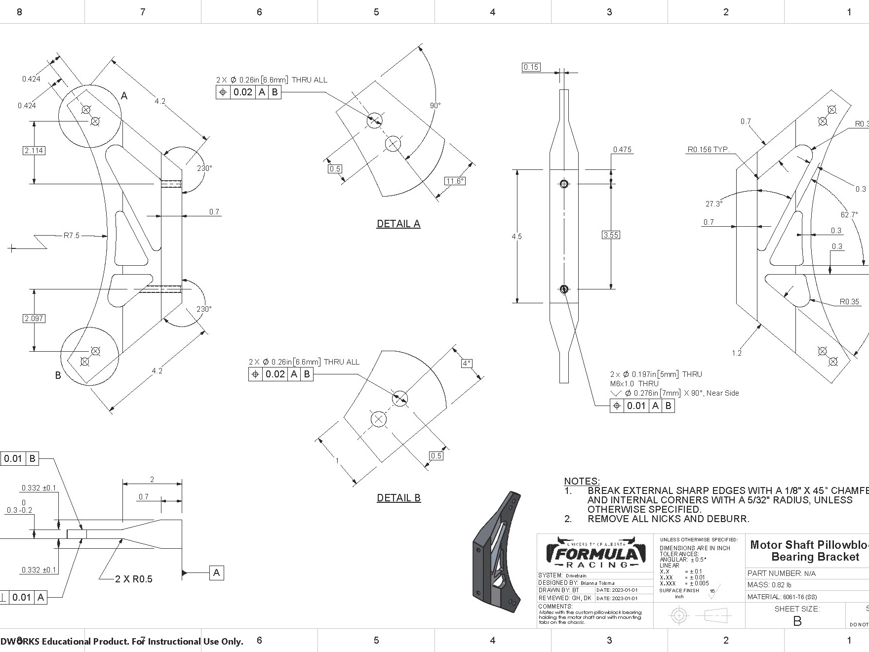
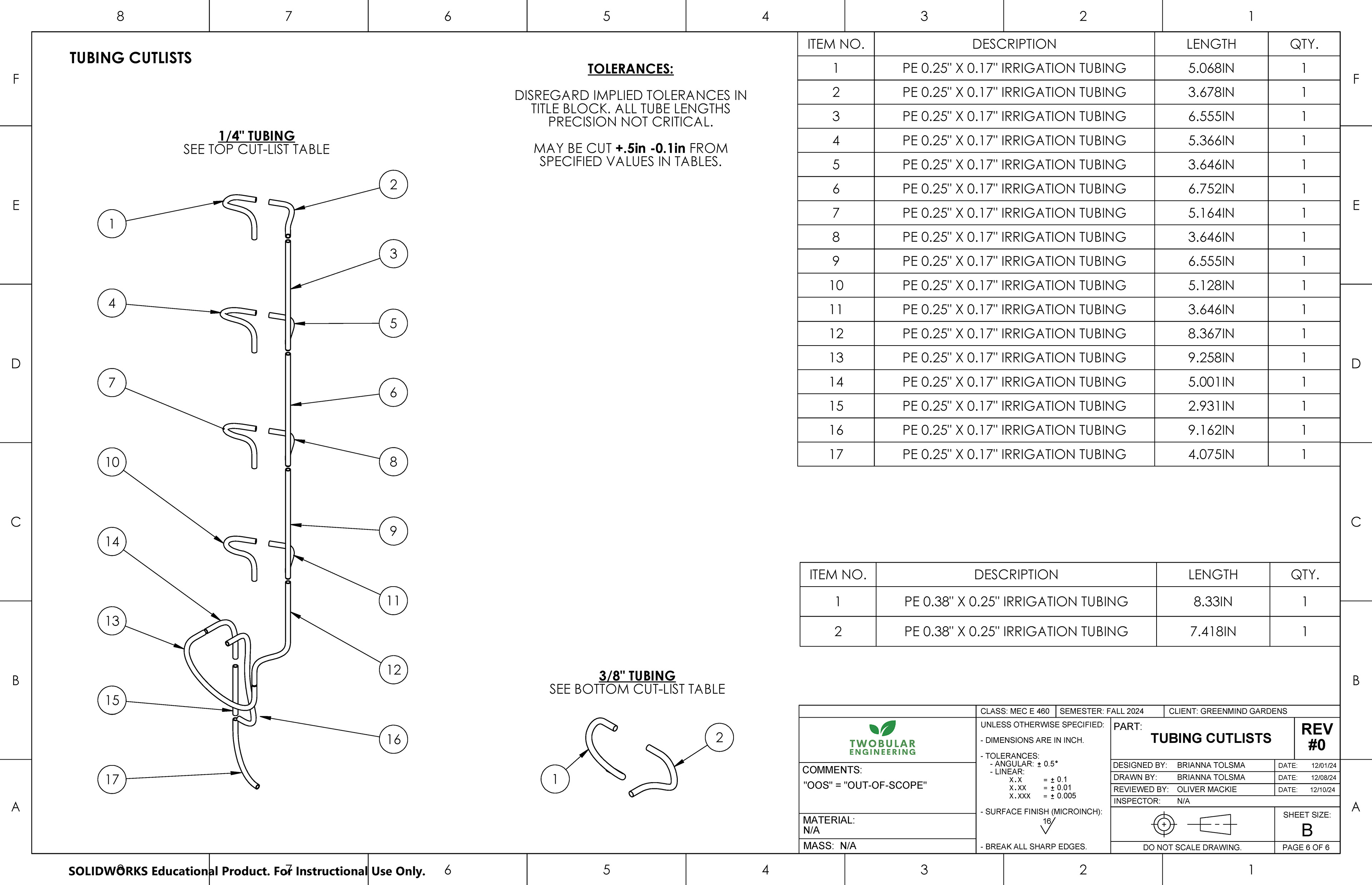
Below is the drawing package I made for the subsystem which shows packaging of the components and the relevant results of the analysis.
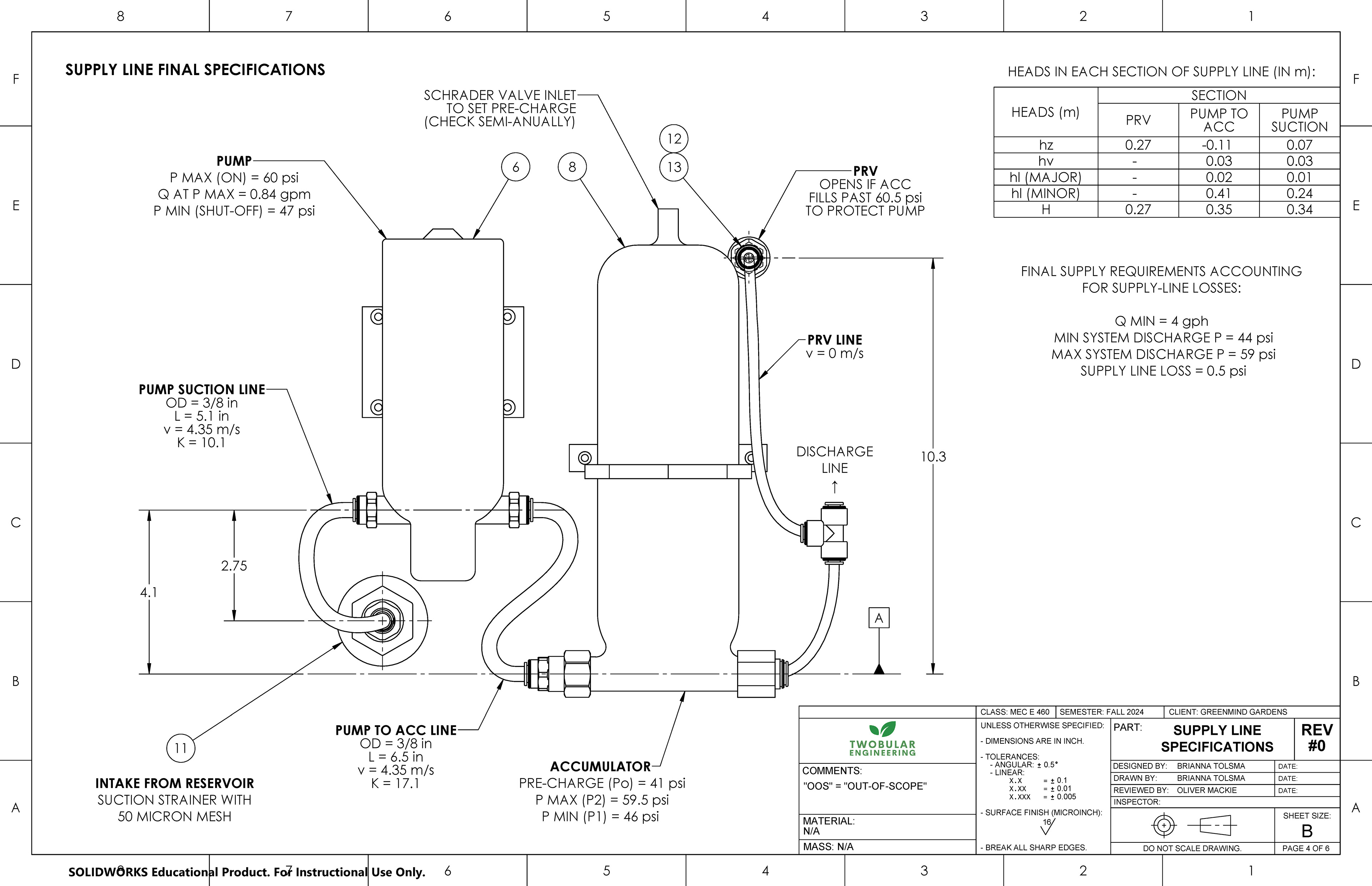
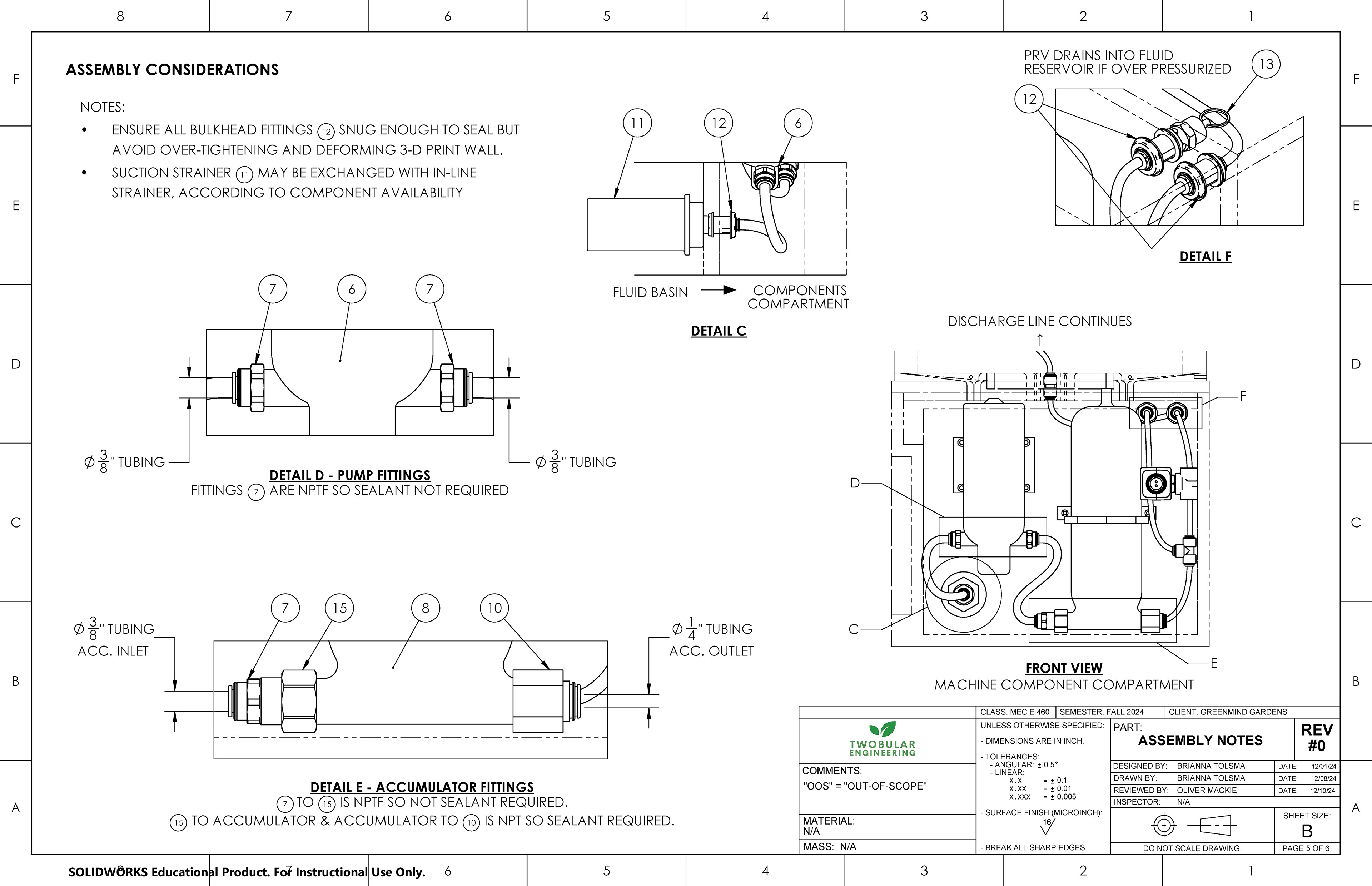
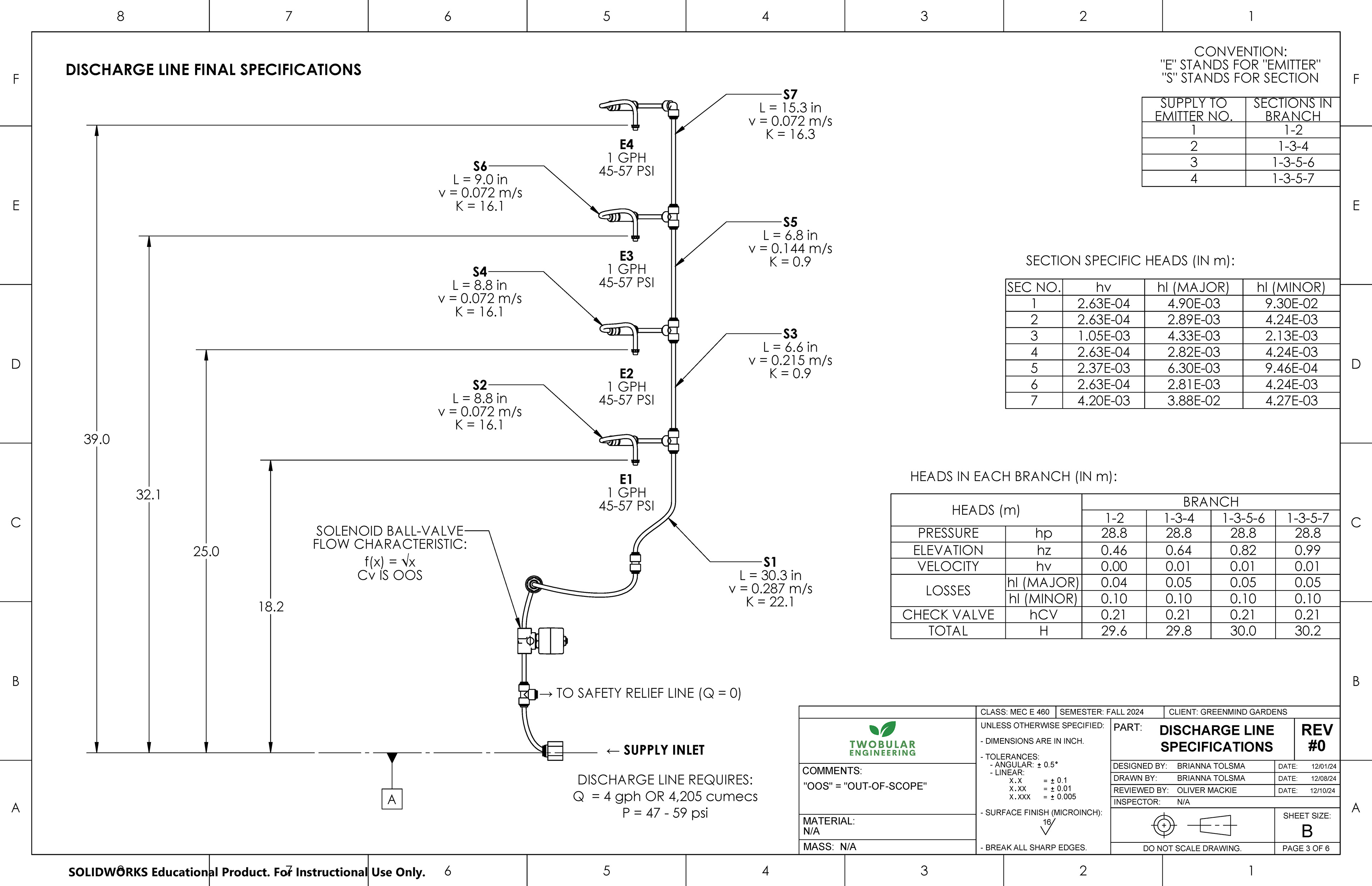
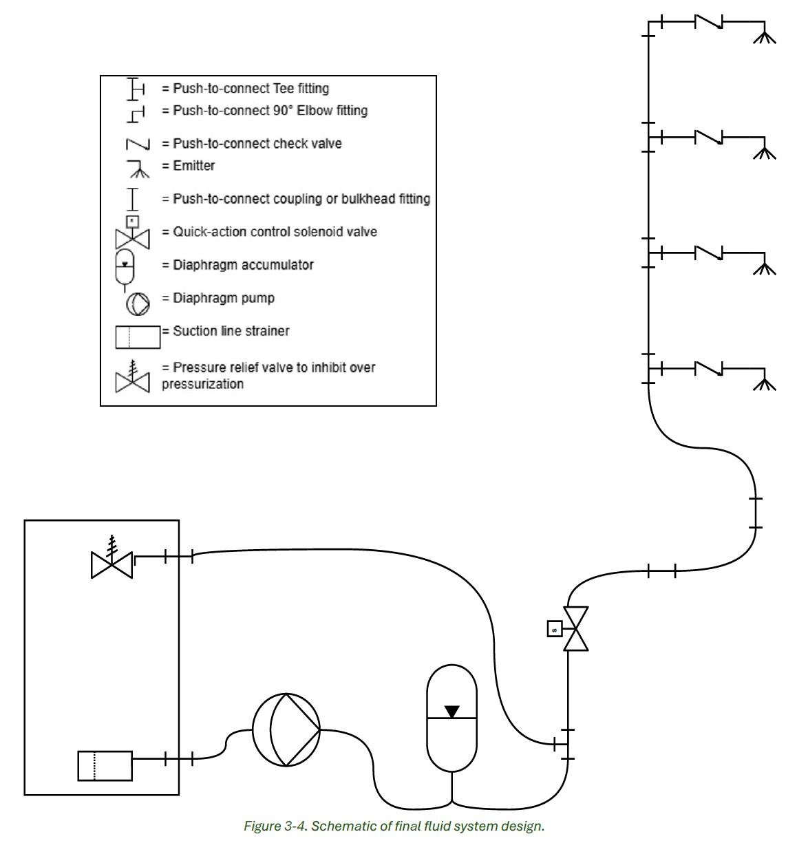
The drawings above include the 3-dimensional finalized subsystem. However, during the design iterations to select components (pump, accumulator, pressure release valve, etc.) I made several 2D schematics. Below is the finalized schematic that the 3D assembly was based on.
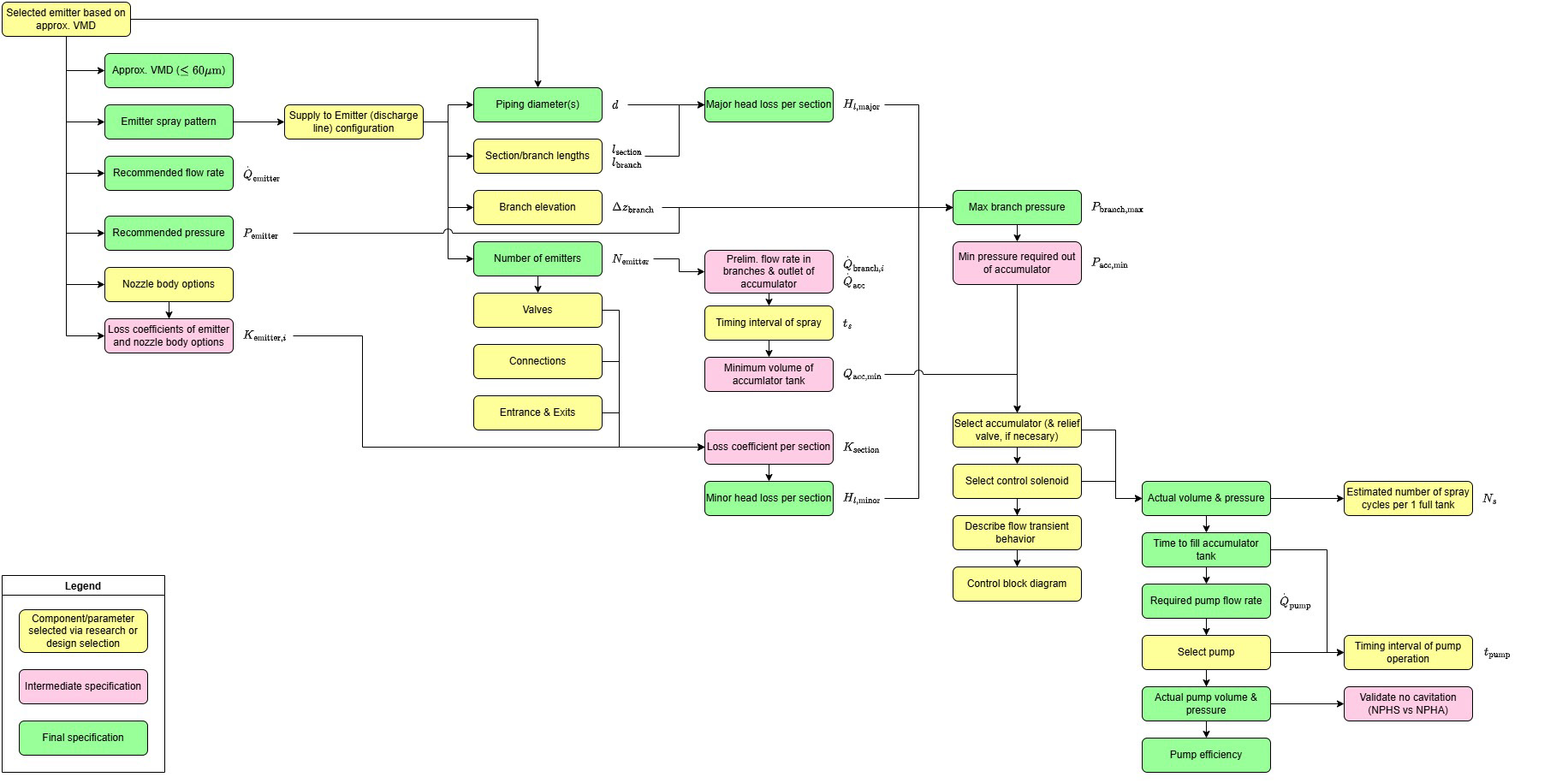
Finally, as my role as the Team Lead, I was also responsible for the project management of all the subsystems. I decided to outline the design process to plan out the dependencies between all subsystems. This was an optional step, but my team and I saw it as a critical one for our project in particular, since most decisions made in one subsystem would affect the design of another.